
വയര്ലെസ്സ് കമ്യൂണിക്കേഷന് ലിങ്ക്
One of the earliest methods of wireless transmission used was with infrared light. Using wireless IR links has many advantages with the primary two being low cost and low part count to implement. The simplest of on/off switches using wireless IR would take no more than 10 parts, but this tutorial will be going to send asynchronous serial data over a wireless IR link.
This tutorial will create a wireless infrared transmitter using an IR LED and a wireless IR receiver using a phototransistor. Asynchronous serial will be transmit over this link at 9600 BPS. The PIC 18F452 will be used to transmit and receiver this data.

Wireless Infrared Link - IR Emitter / Phototransistor 
Wireless Infrared Link - System SetupPurpose & Overview of this project
The goal of this tutorial is to build an IR transmitter and an IR receiver. These two will be a wireless link of one-way asynchronous serial communication at 9600 BPS. To prove the system works the transmitter should count from 0 to 8, sending the count value out the transmitter link to the receiver. The receiver will display the current count value on 8 LEDs. Both the transmitter and receiver will use a PIC 18F452 microcontroller.
In order to create the asynchronous serial communication signals, the transmitter and receiver will use the PIC's USART module to send and receive. The transmitter data will be sent out the IR Emitter LED and, if all is successful, into the phototransistor circuit. The signal will then be input to the transmitter's USART receiver module and the current count displayed on the 8 LEDs.
PIC 18F452 - PIC 18F4520
Two microcontrollers will be used in this tutorial, one for the receiver and one for the transmitter. These will need to be programmed with the software that we will see in that section of this tutorial. I used a PIC 18F452 and 18F4520. These are actually the same and can be used interchangeably.
PICKIT 2
To Load the software onto the PIC microcontroller you will need a programmer. This programmer, called the PICkit2, is very popular and supported by the PIC manufacturer Microchip. It's low cost and will last.
Phototransistor
This component detects the brightness of an infrared light beam. If an infrared LED shines right into a phototransistor, it switches on, otherwise it remains in the off state.
IR Emitter LED
IR Emitter LEDs are found in many places, most commonly in laptops and TV remote controls. These cheap little LEDs are what we will be using to transmit the serial communication data to the receiving phototransistor.
2x 2n2222 Transistors
A small buffer circuit will be created using these general purpose transistors. This will allow us to switch the IR LED on and off with power directly from the power supply.
2x 4 MHz Crystal
Both systems will use a 4 MHz crystal clock, just to make things easier on us. You could use different clock rates for both microcontrollers, just make sure you have the serial communication baud rate set to 9600 BPS.
Wires & Breadboard
These will be used for connecting everything together. If you'd rather use a development board that you have, go ahead, the breadboard just creates a versatile platform that anyone can duplicate this work on.
സര്ക്യൂട്ട് ഡീറ്റെയിലായി കാണുന്നതിന് സര്ക്യൂട്ടില് ക്ലിക്ക് ചെയ്യുക
Schematic Specifics
Power Circuit
The power circuit (regulator) is the same in both transmitter and receiver because all we need a +5v regulated power supply to operate the digital electronics. The 7805 linear regulator was chosen because it is cheap and widely available.
Microcontroller Circuit
The transmitting microcontroller will be a PIC 18F452. The USART module inside of this microcontroller will be used to send the asynchronous serial data. The microcontroller will continuously send a count value from 0 to 8 and then repeat.
Infrared Transmitter Circuit
The PIC's digital USART RC6 Tx output port cannot supply enough current to give the IR emitter LED the power it really needs, so a buffer circuit is used with 2x 2N2222 transistors so that the IR Emitter LED is driven from the main +5v regulated power supply.
സര്ക്യൂട്ട് ഡീറ്റെയിലായി കാണുന്നതിന് സര്ക്യൂട്ടില് ക്ലിക്ക് ചെയ്യുക
Schematic Specifics
Power Circuit
The power circuit (regulator) is the same in both transmitter and receiver because all we need a +5v regulated power supply to operate the digital electronics. The 7805 linear regulator was chosen because it is cheap and widely available.
Microcontroller Circuit
To make things as simple as possible, the receiving microcontroller will be the same as the transmitter: PIC 18F452. The other half of the USART module will be used to receive the data, rather than transmit and then the PIC will decide how many LEDs to light up, 0 to 8, depending upon the transmitted ASCII value, 0 to 8.
Infrared Receiving Circuit
This circuit consists of a photo transistor and 1x 10kΩ resistor with some connections to ground and power. The collector pin of the phototransistor is connected to the PIC's RC7 input also known as the USART Rx input.
The way that the infrared transmitter and receiver pair works is similar to the way that our eyes work. We can see many different colors and depending on what we see, we act. The phototransistor functions in a similar way, it reacts depending upon the intensity of infrared light being shined at it.
 The real difference between the two similar cases above is that our brains already have a way to interpret the different wave lengths of color, where the infrared LED and phototransistor need some intelligent electronics in order to know what to do when certain data is transmitted.Sending Data Over IR
If you're still scratching your head in confusion as to how 0's and 1's can be transmitted using the IR emitter and phototransistor, then build the circuit seen below and it should help make things more clear:
 Here's how the circuit above works: The 9v battery is hooked up to both the IR Emitter and Phototransistor. The IR Emitter, however, is never turned on unless you press the push button. Since the emitter is not powered on, the phototransistor won't allow current to flow through it, so current will instead flow through the red LED. This means until you press the push button, the red LED remains on. After you press the push button, the emitter shines brightly at the phototransistor and the red LED turns off. Here's a video of this circuit in action:
This should give you a much better visual of how digital 0's and 1's can be transmitted wirelessly using these two infrared components. When the red LED shines, you can see a digital 1. When we press the push button and the red LED turns off, that would be a 0.
Now if we replace a steady stream of digital 1's and 0's where the push button is the receiving phototransistor will see the same stream of digital 0's and 1's. Bingo! Wireless transmission. Feed the received stream of digital data into the receiving 18F452 microcontroller and the system is complete.
Hardware DesignThe hardware section, where I'll show you how I built the transmitter and receiver is split into two sections, one for the transmitter and one for the receiver. Below are detailed descriptions and pictures of my step by step construction of the transmitter.
Building The Circuit
I always like to begin assembling a circuit by having all the parts for it laid out in front of me. When working with a breadboard a pair of needle-nose pliers can also be helpful for getting wires into the breadboard holes.


 Hopefully that was seemingly painless, the circuit is not too complex and therefore fits nicely on a breadboard. Now let's make the receiver!
Wireless Infrared Communication Link System
Introduction
This article explains how to create a wireless infrared transmitter using an IR LED and a wireless IR receiver using a phototransistor to make a communication system. Asynchronous serial is transmitted over this link at 9600 BPS. Two PIC 18F452's are used to transmit and receive the data.One of the earliest methods of wireless transmission used was with infrared light. Using wireless IR links has many advantages with the primary two being low cost and low part count to implement. The simplest of on/off switches using wireless IR would take no more than 10 parts, but this tutorial will be going to send asynchronous serial data over a wireless IR link.
This tutorial will create a wireless infrared transmitter using an IR LED and a wireless IR receiver using a phototransistor. Asynchronous serial will be transmit over this link at 9600 BPS. The PIC 18F452 will be used to transmit and receiver this data.

Wireless Infrared Link - IR Emitter / Phototransistor

Wireless Infrared Link - System Setup
The goal of this tutorial is to build an IR transmitter and an IR receiver. These two will be a wireless link of one-way asynchronous serial communication at 9600 BPS. To prove the system works the transmitter should count from 0 to 8, sending the count value out the transmitter link to the receiver. The receiver will display the current count value on 8 LEDs. Both the transmitter and receiver will use a PIC 18F452 microcontroller.
In order to create the asynchronous serial communication signals, the transmitter and receiver will use the PIC's USART module to send and receive. The transmitter data will be sent out the IR Emitter LED and, if all is successful, into the phototransistor circuit. The signal will then be input to the transmitter's USART receiver module and the current count displayed on the 8 LEDs.
Parts List Details
Some of the parts seen above maybe be familiar to you, but if any of them are not you can see a picture of it above. Below I have a better description of the main parts used in this tutorial.PIC 18F452 - PIC 18F4520
Two microcontrollers will be used in this tutorial, one for the receiver and one for the transmitter. These will need to be programmed with the software that we will see in that section of this tutorial. I used a PIC 18F452 and 18F4520. These are actually the same and can be used interchangeably.
PICKIT 2
To Load the software onto the PIC microcontroller you will need a programmer. This programmer, called the PICkit2, is very popular and supported by the PIC manufacturer Microchip. It's low cost and will last.
Phototransistor
This component detects the brightness of an infrared light beam. If an infrared LED shines right into a phototransistor, it switches on, otherwise it remains in the off state.
IR Emitter LED
IR Emitter LEDs are found in many places, most commonly in laptops and TV remote controls. These cheap little LEDs are what we will be using to transmit the serial communication data to the receiving phototransistor.
2x 2n2222 Transistors
A small buffer circuit will be created using these general purpose transistors. This will allow us to switch the IR LED on and off with power directly from the power supply.
2x 4 MHz Crystal
Both systems will use a 4 MHz crystal clock, just to make things easier on us. You could use different clock rates for both microcontrollers, just make sure you have the serial communication baud rate set to 9600 BPS.
Wires & Breadboard
These will be used for connecting everything together. If you'd rather use a development board that you have, go ahead, the breadboard just creates a versatile platform that anyone can duplicate this work on.
Schematic Overview
Two circuits need to be built for this tutorial; the transmitter and the receiver. These two circuits are not over-complex in anyway so hopefully acquiring the parts and assembling everything should be straight forward. The main parts to take note of in these two circuits are the 7805, 18F452, 2N2222, Phototransistor and IR Emitter LED.സര്ക്യൂട്ട് ഡീറ്റെയിലായി കാണുന്നതിന് സര്ക്യൂട്ടില് ക്ലിക്ക് ചെയ്യുക
Schematic Specifics

Power Circuit
The power circuit (regulator) is the same in both transmitter and receiver because all we need a +5v regulated power supply to operate the digital electronics. The 7805 linear regulator was chosen because it is cheap and widely available.
Microcontroller Circuit
The transmitting microcontroller will be a PIC 18F452. The USART module inside of this microcontroller will be used to send the asynchronous serial data. The microcontroller will continuously send a count value from 0 to 8 and then repeat.
Infrared Transmitter Circuit
The PIC's digital USART RC6 Tx output port cannot supply enough current to give the IR emitter LED the power it really needs, so a buffer circuit is used with 2x 2N2222 transistors so that the IR Emitter LED is driven from the main +5v regulated power supply.
സര്ക്യൂട്ട് ഡീറ്റെയിലായി കാണുന്നതിന് സര്ക്യൂട്ടില് ക്ലിക്ക് ചെയ്യുക
Schematic Specifics

Power Circuit
The power circuit (regulator) is the same in both transmitter and receiver because all we need a +5v regulated power supply to operate the digital electronics. The 7805 linear regulator was chosen because it is cheap and widely available.
Microcontroller Circuit
To make things as simple as possible, the receiving microcontroller will be the same as the transmitter: PIC 18F452. The other half of the USART module will be used to receive the data, rather than transmit and then the PIC will decide how many LEDs to light up, 0 to 8, depending upon the transmitted ASCII value, 0 to 8.
Infrared Receiving Circuit
This circuit consists of a photo transistor and 1x 10kΩ resistor with some connections to ground and power. The collector pin of the phototransistor is connected to the PIC's RC7 input also known as the USART Rx input.
The Theory
The core infrared theory for getting this tutorial working was already described in the Infrared Receiver tutorial, so I'll run through an abridged version here. First I'll describe as an overview what infrared is and how it relates to our lives, then I'll go further to how we can transmit digital data over this wireless link.The way that the infrared transmitter and receiver pair works is similar to the way that our eyes work. We can see many different colors and depending on what we see, we act. The phototransistor functions in a similar way, it reacts depending upon the intensity of infrared light being shined at it.
If you're still scratching your head in confusion as to how 0's and 1's can be transmitted using the IR emitter and phototransistor, then build the circuit seen below and it should help make things more clear:
This should give you a much better visual of how digital 0's and 1's can be transmitted wirelessly using these two infrared components. When the red LED shines, you can see a digital 1. When we press the push button and the red LED turns off, that would be a 0.
Now if we replace a steady stream of digital 1's and 0's where the push button is the receiving phototransistor will see the same stream of digital 0's and 1's. Bingo! Wireless transmission. Feed the received stream of digital data into the receiving 18F452 microcontroller and the system is complete.
Hardware DesignThe hardware section, where I'll show you how I built the transmitter and receiver is split into two sections, one for the transmitter and one for the receiver. Below are detailed descriptions and pictures of my step by step construction of the transmitter.
Building The Circuit
I always like to begin assembling a circuit by having all the parts for it laid out in front of me. When working with a breadboard a pair of needle-nose pliers can also be helpful for getting wires into the breadboard holes.
The first step is getting the power regulation circuit on the breadboard.
Afterward we add the PIC circuitry, with a crystal and 10kΩ resistor.
Now, I added the first 2n2222 buffer stage for the IR output.

The final step is adding the 2nd part of the 2n2222 buffer stage, and IR Emitter.
Wireless Infrared Communication Link System Hardware - Infrared Receiver |
| Hardware DesignIn the second part of the hardware section we will look at how the receiver was built step by step. Follow along with the schematic and you'll get a good feeling for how things come together and the stages I use when building electronics on a breadboard. Building The Circuit Just like before, I laid out all the parts on my workbench, ready to be assembled into the breadboard. The receiver does have significantly more parts, so it will take a little longer to get this one right.  Start by assembling the power regulation (7805) circuit on the breadboard.  The PIC circuit is added next with 4 MHz crystal and 10kΩ resistor.  Resistors are added to each pin of PORTD on the PIC for output.  LEDs are connected to the resistors and then to ground. The final step is connecting the RX pin on the PIC to the phototransistor.  After some effort, the circuit has been built on the breadboard and is ready for some software. |
Wireless Infrared Communication Link System Software |
| The SoftwareThere are two main portions of code that we are concerned with: Transmitter Code Transmits USART Serial Data Receiver Code Receives and Translates USART Data Since this circuit operates as if the transmitter and receiver were connected directly with a wire, the software has nothing out of the ordinary. The transmitter is constantly counting 0 to 8 over and over, and the receiver is parsing this input and lighting up the corresponding LEDs, over and over. Infrared Link Transmitter Code ------------« Begin Code »------------ void main(void){------------« End Code »------------ There really are no surprises here. The transmitter is setup with a routine and simple while loop that counts then transmits, then counts and then transmits over and over until infinity.Infrared Link Receiver Code ------------« Begin Code »------------ void main(void)------------« End Code »------------ The receiver does the same thing as the transmitter just with the opposite function: receiving. It continually checks to see if data is ready in the USART receiver buffer. When data is accepted, it is then evaluated and the LEDs updated to output the change.Program Download: Main C File wireless_serial_tx.c wireless_serial_rx.c wireless_serial_tx.hex wireless_serial_rx.hex Data & Observations After all that pain-staking work of building a transmitter and receiver for this wireless infrared link, let's give it a test and see how things work. The video below shows me turning on both systems and then testing them out. The video should convince you that information is indeed being transferred over the infrared wireless link and that I'm not somehow fooling you =P. When the transmitter or receiver is moved outside of the line-of-sight, the system no longer works. This is an unfortunate characteristic of IR transmission, but it is a small price to pay for how easy it is to implement. An Overview Of The Wireless Infrared LinkIn comparison to other wireless transmitter and receiver systems, this wireless infrared link is extremely low cost and easy to build. Many limitations exist, like the need to have line of sight, transmitter to receiver, however even with these limitations there are many applications for this type of wireless system. The IR link created in this tutorial showed you how easy it can be and how standard digital communication can be passed across the link. This was just a simple example, but it should be enough to get anyone started for bigger and better things with wireless IR.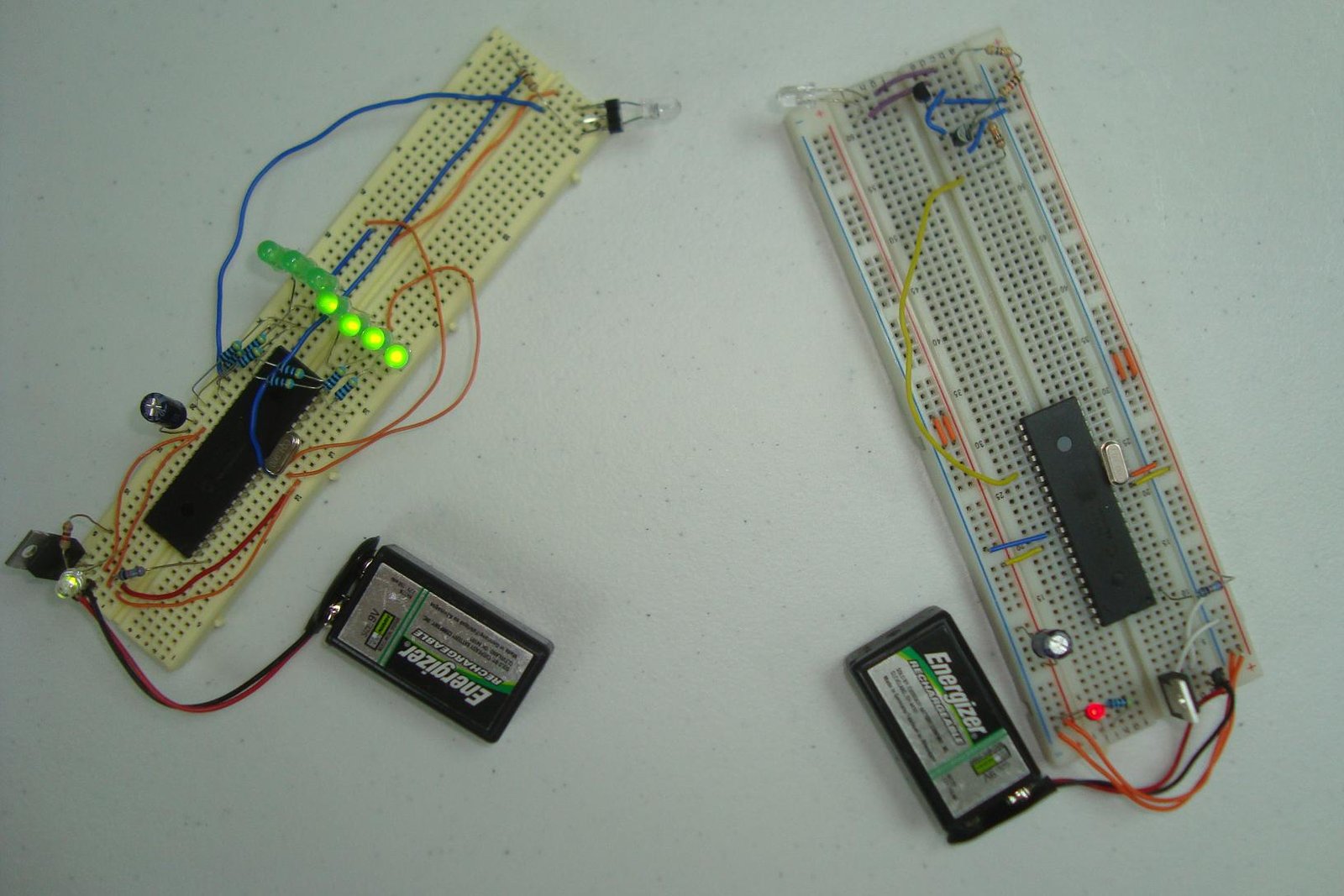 The next steps you could take, lead to many different directions. With the knowledge in this tutorial you can move forward and try to amplify the received signal so the transmitter and receiver don't have to be so close together, that is how TV remote control IR works. You can further experiment with the upper limits of how fast you can transfer data and how far with what accuracy. Since the parts are so low cost, the real limitation is only your imagination and desire to solve your wireless problems. Conclusion This was probably one of the more fun tutorials that I have written. Wireless, at least from the analog perspective, is usually a gigantic headache but when you move to an infrared based wireless system you don't have to deal with as much RF theory. This means more digital design, less analog design which is very welcome. The tutorial was successful as the data section showed you and hopefully you will now go and build your own wireless infrared link! |
No comments:
Post a Comment